Explain different types of filters used with rectifier circuits
We have learned the Types of filter circuits used with rectifiers concerning changing a curving ac voltage into its corresponding pulsing dc. aside from the filter
this pulsing dc voltage can
have unwanted ac parts just like the parts of its offer frequency in
conjunction with its harmonics (together referred to as ripples). These ripples
are going to be the best for a single-phase 0.5-wave rectifier and can cut back
more for a single-phase full-wave rectifier. The ripples are going to be the minimum for 3-phase rectifier circuits. Such an offer doesn't help drive advanced electronic circuits. for many offer functions, constant dc voltage is
needed than the rhythmic output of the rectifier. for many applications, the
provision from a rectifier can build the operation of the circuit poor. If the
rectifier output is ironed and steady and so passed on because of the offer
voltage, then the operation of the circuit becomes higher. Thus, the output of
the rectifier must be passed tho' a filter circuit to filter the ac parts.
The filter may be a
device that permits passing the dc part of the load and blocks the ac part of
the rectifier output. therefore the output of the filter circuit is going to
be a gentle dc voltage.
The filter circuit
is often made of a mixture of parts like capacitors, resistors, and
inductors. inductance is employed for its property that it permits solely dc
parts to pass and blocks ac signals. the electrical condenser is employed therefore
on the block the dc and permits ac to pass. All the combos and their operations are
explained intimately below.
Series inductor filter formula
The circuit diagram of a full-wave rectifier with a
series inductance filter is given below.
 |
| full-wave rectifier |
As the name of the
filter circuit suggests, the inductance L is connected serial between the
rectifier circuit and also the load. The inductance carries the property of
opposing the amendment in the current that flows through it.
In alternative
words, the inductance offers high ohmic resistance to the ripples and no ohmic
resistance to the specified dc parts. therefore the ripple parts are going to
be eliminated. once the rectifier output current will increase on top of an
exact worth, energy is kept in it within the type of field of force and this
energy is given up once the output current falls below the typical worth.
therefore all the unexpected changes in current that happen within the circuit
are going to be ironed by inserting the inductance serial between the rectifier
and also the load.
The wave Formula of inductance
From the circuit,
for zero frequency dc voltage, the choke resistance RI serial with the load
resistance RL forms a potential divider circuit, and therefore the dc voltage
across the load is
Vdc = RL/(Ri + RL)
Vdc is the
output from a full-wave rectifier. during this case, the worth of RI is
negligibly little when put next to RL.
The result of upper
harmonic voltages is often simply neglected as higher filtering for the upper
harmonic parts manifests itself. this is often a result of the very fact that
with the rise in frequency, the electrical phenomenon of the inductance
conjointly will increase. It ought to be noted that a decrease within the worth
of load resistance or a rise within the worth of load current can decrease the
number of ripples within the circuit. So, the series inductance filter is
generally utilized in cases of high load current or little load resistance. an
easy series inductance filter might not be properly used. it's forever higher
to use a shunt electrical condenser (C) with series inductance (L) to make an AN
LC Filter.
Shunt capacitor filter
As the name
suggests, an electrical condenser is employed because the filter and this high-worth electrical condenser are shunted or placed across the load ohmic
resistance. This electrical condenser, once placed across a rectifier gets
charged and stores the charged energy throughout the physical phenomenon
amount. once the rectifier isn't conducting, this energy charged by the
electrical condenser is delivered back to the load. Through this energy storage
and delivery method, the time length throughout that this flows through the
load electrical device gets hyperbolic, and also the ripples are remittent by a
good quantity. therefore for the ripple part with a frequency of ‘if megacycle,
the electrical condenser ‘C’ can supply an awfully low ohmic resistance. the
worth of this ohmic resistance is often written as follows:
Shunt electrical condenser ohmic resistance = 1/2 fC
Thus the dc parts of
the signal in conjunction with the few residual ripple parts are merely allowed
to travel through the load resistance RLoad. The high quantity of ripple parts
of current gets bypassed through the electrical condenser C.
Now allow us to
investigate the operation of Half-wave rectifiers and rectifiers with electrical
condenser filters, their output filtered wave, ripple issue, deserves, and
demerits intimately.
Half-wave Rectifier with condenser Filter
 |
| Half-wave Rectifier |
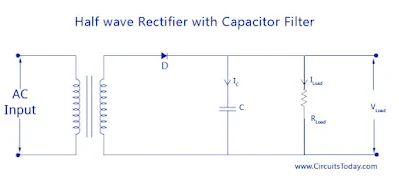
The circuit diagram on
top shows a half-wave rectifier with a condenser filter... The output of the
RLoad is VLoad, the present through its ILoad. the present through the
condenser is Ic.
During the positive
0.5 cycles of the input ac voltage, the diode D is going to be forward biased
and therefore starts conducting. throughout this era, the condenser ‘C’ starts
charging to the utmost price of the availability voltage Vsm. once the
condenser is totally charged, it holds the charge till the input ac offered to
the rectifier reaches the negative 0.5 cycles. As shortly as the negative
0.5 offer is reached, the diode gets reverse-biased and therefore stops
conducting. throughout the non-conducting amount, the condenser ‘C’ discharges
all the keep charges through the output load resistance RLoad. because the
voltage across RLoad and the voltage across the condenser ‘C’ area unit
constant (VLoad = Vc) decrease exponentially with a time constant
(C*RLoad) on the curve of the non-conducting amount. this can be shown in
the graph below.
The value of the
discharge time constant (C*RLoad) being terribly massive, the condenser ‘C’
won't have enough time to discharge properly. As shortly as the condenser
starts discharging, the time becomes over. therefore {the price|the worth} of
RLoad at the discharge time also will be high and have simply a touch less
value than the output of RLoad. this can be done once the positive 0.5 cycle repeats
once more and also the diode starts conducting. The condition to be thought of
at this stage is that the corrected voltage takes price quite the condenser
voltage. once the condition happens the condenser starts charging a price
of Vsm. The condition once more changes once the negative 0.5 cycle comes into
pace, and also the whole cycle is once more continual to make the output wave
shape as shown on top. The output shows an almost constant dc voltage at the
load and the output voltage is inflated significantly.
• If the worth of load resistance is
massive, the discharge time constant is going to be of a high price, and
therefore the capacitors’ time to discharge can live through shortly. This
lowers the number of ripples within the output and will increase the output
voltage. If the load resistance is tiny, the discharge time constant is going
to be less, and also the ripples are going to be a lot with a decrease in
output voltage.
• The price of the condenser used plays
a crucial role in deciding the output ripples and also the average dc level. If
the condenser price is high, quantity|the quantity|the number} of charge it
will store are going to be high, and also the amount it discharges are going to
be less. therefore the ripples are going to be less and also the average dc
level is going to be high. But, there's a limit on what quantity capacitance
will b inflated. If the condenser price is inflated to a really high price, the current needed to charge the condenser to a given voltage is going
to be high. This price of current depends on the manufacturer of the diode and
can be certainly restricted to a precise price. Thus, there's a limit in
increasing the condenser price in a very half-wave rectifier shunt condenser
filter circuit.
• Poor voltage regulation.
Ripple issue
The rms price depends
on the height price of charging and discharging magnitude, Vpeak.
Vac rms = Vpeak/2
Vpeak = Idc/fC
Ripple issue = holiday
rms/Vdc = (Vpeak/2 ) * (1/Idc.RLoad)
= Idc/(2
.Idc.RLoad.f.C) = 1/(2 fCRLoad)
Rectifier
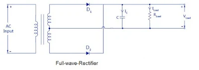
with Shunt condenser Filter
The circuit diagram of
a rectifier with a condenser filter is shown below.
The filter condenser C
is placed across the resistance load RLoad. the full operating is just about
the same as that of a half-wave rectifier with a shunt condenser explained on top
of it. the sole distinction is that 2 pulses of current can charge the condenser
throughout alternate positive (D1) and negative (D2) 0.5 cycles. equally
condenser C discharges doubly through RLoad throughout one full cycle. this can
be shown within the wave shape below.
The load current
reduces by a smaller quantity before the ensuing pulse is received as there area
unit of a pair of current pulses per cycle. This causes an honest reduction in
ripples and an extra increase within the average dc load current.
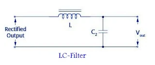
L-C Filters
 |
| L-C Filters |
In the straightforward
shunt capacitance, the filter circuit is explained higher than, we've ended that the
capacitance can scale back the ripple voltage, however, causes the diode current
to extend. This large current could harm the diode and can additionally cause heating
drawbacks and reduce the potency of the filter. Conversely, an easy
series inductance reduces the height and effective values of the output
current and output voltage. Then if we tend to mix each filter (L and C), a
replacement filter referred to as the L-C filter may be designed which can have an honest potency, with restricted diode current and enough ripple
removal issue. The voltage stabilizing action of shunt capacitance and also the
current smoothing action of series inductance filter may be combined to create
an ideal sensible filter circuit.
L-C filters may be of
2 types: Choke Input L-section Filter and L-C capacitance input filter
Choke Input L-Section
Filter
An inductance filter
will increase the ripple issue with the rise in load current Reload. A
capacitance filter has an AN reciprocally proportional ripple issue with the relevancy
load resistance. Economically, each inductance filter and capacitance filter
don't seem to be appropriate for prime finish purpose
L-C inductance input
or L-section filter consists of AN inductance ‘ L’ connected nonparallel with a
[*fr1] or full-wave rectifier and a capacitance ’C’ across the load.
As shown within the
circuit diagram higher than, the inductance L permits the dc to pass however
restricts the flow of ac parts as its dc resistance is extremely tiny and ac
electric resistance is massive. once a sign passes through the choke, if
there's any fluctuation remaining in present, it'll be absolutely bypassed
before it reaches the load by the shunt capacitance as a result of the worth of
Xc being way smaller than Reload. quantity|the quantity} of ripples may be reduced
to an excellent amount by creating the worth of XL larger than Xc at ripple
frequency.
Ripple issue
Ripple issue =
vacation rms/Vdc = (√2/3)(Xc/XL) =
(√2/3)(1/[2wc])(1/[2wL]) = 1/(6√2w2LC)
Though the L-C filter
has these blessings, it's currently become quite obsolete due to the massive
size of inductors and its price of production. Nowadays, IC voltage regulators
square measure a lot of ordinarily used together with active filters, that
scale back the ripples and keep the output dc voltage constant.
The diagram of the L-C
capacitance input filter and the waveform is shown below.
Π – Filter or Capacitance Input Filter
The name pi – Filter
implies the alikeness of the circuit to a Π form with 2 shunt capacitances
(C1 ANd C2) and an inductance filter ‘L’. because the rectifier output is
provided directly into the capacitance it is additionally referred to as a
capacitance input filter.
The output from the
rectifier is 1st given to the shunt capacitance C. The rectifier used may be
[*fr1] or full-wave and also the capacitors square measure sometimes
electrolytic even though they are massive in size. In sensible
applications, the 2 capacitances square measure embowered in a very metal
instrumentality that acts as a standard ground for the 2 capacitors. Circuit diagram
and also the wave when compared to an alternative style of filters, the Π – Filter
has some blessings like higher dc voltage and smaller ripple issue. however, it
additionally has some disadvantages like poor voltage regulation, high peak
diode current, and high peak inverse voltage.
This filter is split
into 2 – a capacitance filter and an L-section filter. The capacitance C1 will do most of the filtering within the circuit and also the remaining ripple is
removed by the L-section filter (L-C2). C1 is chosen to supply terribly low
electrical phenomenon to the ripple frequency. The voltage regulation is poor
for this circuit because the output voltage falls off the chop-chop with the rise
in load current.
Ripple issue
Ripple issue =
√2/(8w3C1C2LRload)
R-C Filter
 |
| R-C Filter |
We have already
mentioned the drawbacks of employing a pi-filter. the most reason for these drawbacks is that the use of inductance within the filter circuit. If
we tend to use a resistance nonparallel, rather than the inductance because of the
filter, these drawbacks may be overcome. so the circuit is known as an R-C
filter. during this circuit, the ripples need to be created to drop across the
resistance R rather than the load resistance RL. For this, the worth of RL is
unbroken and abundant and larger than the worth of the electrical phenomenon of capacitance
C2 (XC2). this implies that every section reduces the ripple by an element of a
minimum of ten.
form square measure has given below.
Though the circuit
nullifies the bound drawbacks of the pi-filter, the circuit on its own has some
issues also. The filter has terribly poor voltage regulation. there's an
oversized free-fall within the resistance R. The circuit additionally develops
loads of warmth and this needs to be dissipated through enough and adequate
ventilation. Thus, the filter is just appropriate for little load current or
massive load resistance circuits.


0 Comments
Leave a Reply...