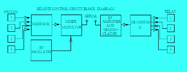
Home automation is a very interesting project idea nowadays in electronics. To control any light or fan by remote control we have to use relays in addition to switching.
The light can be control by relay only or relay and the switch depends on the wiring of the relay/switch. To control light with both switch and relay we need a two-way switch and a relay with change over contact.
Basics of remote control:-
There are mainly two parts: the handheld remote control unit and the other is the receiver unit. This remote works for a distance of 10 feet's normally. The remote control has a set of pushbuttons to give on-off commands. The signal from the remote is sent to the receiver by radio waves/ infrared waves or a blue tooth system. TV remote uses infrared signals. Small toys car/drones use radio waves. DTMF signal is also used in some systems where more items (channel) are controlled. In the case of blue tooth control, we can use the mobile phone as a remote control with some remote apps. So based on the medium of signal sending remote control can be of the following types
Infrared remote control:- Uses infrared rays as a medium.
Radiofrequency remote control:- it uses radiofrequency as a carrier for signal. The blue tooth also uses radiofrequency. 27 MHz trans receiver modules are also available for remote control.
 |
| Remote control switch circuit diagram |
Mobile SMS-based:- this system uses a GSM mobile module with a sim card. With a mobile phone, SMS is sent to the Gsm module. This message is decoded by the Arduino microcontroller and operates different relays to control appliances.
Main steps in working
Pushbuttons/Switches:- we can use a single button/switch to on/off a light or two-button separately for on and off operation. To control 4 lights we need 4 buttons in the first system and need 8 buttons in the second system.Coding button signal:- The 5v signal from the button goes to coding IC which generates a digital signal corresponding to that button
Note above is a general description but different remote control may use somewhat different logics for control.


0 Comments
Leave a Reply...